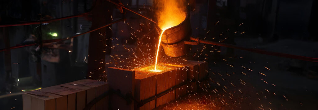
Design Considerations for High‑Pressure Die Casting of Complex Components
High-pressure die-casting (HPDC) tooling can cost $60 000–$250 000. The only cheap moment to make changes is before tool-steel is cut. Follow these rules and you will avoid late weld repairs, extra machining, and frantic schedule slips.
Keep Wall Thickness Uniform
Metal shrinks as it solidifies. If one area is thick and another is thin, the thick “hot spot” cools last and can tear open tiny cavities called shrinkage porosity.
| Alloy (example) | Best wall thickness | Allowed variation |
|---|---|---|
| Aluminium AlSi10Mg | 2.5–3 mm | ± 20 % |
| Magnesium AZ91D | 2–2.5 mm | ± 15 % |
| Zinc (Zamak 3) | 1–1.5 mm | ± 10 % |
Design tip: If you must move from thick to thin, taper gradually—one millimetre thinner for every four millimetres of length. Add ribs (shallow reinforcing fins) for strength instead of adding extra metal.
Add Draft Angles so the Part Releases
Draft is a slight taper that lets the finished part slide out of the die without scraping.
Outside walls (the “A-side”): at least 0.5 °.
Inside walls or deep pockets: 1–2 °.
Surfaces with decorative texture: add 1 ° extra draft for every 0.05 mm of texture depth.
Fewer parting lines mean less tooling cost, so try to design the part to open in one primary split plane. Use local side cores only where truly necessary.
Size Ribs and Bosses Correctly
Ribs: thin reinforcing fins. Make them about 60 % of the main wall thickness so they fill well yet do not trap heat.
Bosses: raised cylinders for screws or dowels.
Fillet radius (rounded corner) where the boss meets the wall should be at least one-quarter of the wall thickness.
Heel radius—a second, larger radius at the very base—should equal half the wall thickness. These curves keep metal flow smooth and reduce cracking in the die.
Control How Fast Metal Enters
If molten metal shoots through the gate (the narrow opening into the cavity) faster than 0.5 metres per second (≈ 1.6 ft s⁻¹), its thin oxide skin folds over and traps air. The result is X-ray-visible porosity.
Fix: Calculate the gate cross-section so metal speed is ≤ 0.5 m s⁻¹ at entry, then let it speed up inside the cavity to finish filling in under 0.06 s.
Runner layout: Use a tapered supply channel that feeds into fan-shaped gates. This lets metal spread in a single front rather than two streams colliding head-on.
Give Air Somewhere to Go—Overflows & Vents
Metal always pushes air out of the die. Without a path, that air becomes gas pockets.
Overflow pockets (small scrap pools) should hold at least 30 % of the gate volume so they capture the first, least-clean metal.
Vent lands—razor-thin slots—should be 0.02 mm thick or less so air escapes but metal “freezes” and cannot leak out.
Place overflows opposite the gates so air travels the full cavity length before it vents.
Side Cores (Slides) Done Right
Sometimes undercuts demand a movable insert called a side core or slide.
Keep slide travel (“stroke”) under 60 mm; shorter moves are faster and more reliable.
Tip of the slide should be an H-13 steel insert that has been nitrided (surface-hardened) so molten aluminium will not solder to it.
Add small kiss-off pads—flat spots that touch the casting under pressure—to stop the slide from flexing.
Plan Machining Stock Up-Front
Even “near-net-shape” castings need some machining.
| Feature | Extra metal to leave for final machining |
|---|---|
| Flat datum pad | 0.6 mm |
| Hole to be reamed | 1.0 mm |
| O-ring groove | 0.3 mm |
Cast the datum pads right onto the part. Your CNC mill can clamp on them without extra welding or fixturing.
Simulate Filling and Solidification in High-Pressure Die Casting
A basic computer simulation costs about $1 000 and often saves $20 000–$40 000 in late die re-cuts.
Goal: make the last-to-fill corner land in an overflow—not in a critical wall.
Keep temperature spread at that point under 3 °C.
Control Die Temperature
Cooling channels: Ø 10 mm, drilled 10 mm below the cavity surface.
Switch to oil (instead of water) for local hot areas expected to hit > 280 °C.
Die spray: about 0.15 s of lubricant, followed by 0.05 s of air to blow off excess—prevents sticking without chilling the die.
Add a Vacuum Port for Near-Porosity-Free Parts
A simple 6 mm-diameter port connected to a vacuum pump can pull cavity pressure down to 30 mbar (about 3 % of normal atmospheric pressure) before metal arrives. This removes ~99 % of trapped air.
Place the port at the furthest end of the fill path so the airflow helps sweep gas ahead of the metal.
Use One Datum Framework for Tolerances
Apply GD&T (Geometric Dimensioning & Tolerancing) from a single, cast-in datum reference. If the very first machining operation can be done while the part is still attached to its casting “tree,” you slash stack-up errors.
Validate with a Simple Test Plan
Short-shot study—inject partial shots to verify the metal flow path matches simulation.
Measure 30 parts; aim for Cp ≥ 1.33 (well-centered tolerances).
X-ray one casting every 1 000 shots for the first 10 000 pieces, then switch to statistical sampling at 1 %.
