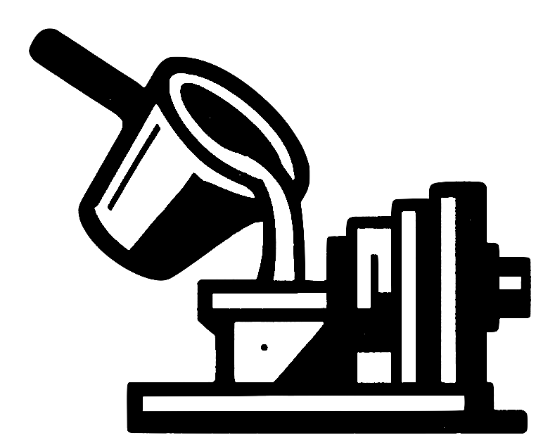
Bubble Trail Porosity Unmasked
Introduction
Bubble trail porosity sits at the heart of many “mystery” failures in high‑pressure and low‑pressure die casting. These elongated, oxide‑lined cracks start life as rising gas bubbles that leave collapsed tubes—trails—inside the solidifying metal. Once mistaken for harmless shrinkage, bubble trails concentrate stress, leak under pressure and slash elongation. This article explains their anatomy, formation, diagnostic signatures, and the proven shop‑floor controls that today’s manufacturing engineers can apply to consign them to history.
Understanding Bubble Trail Porosity
The passage of a single bubble through an oxidisable melt is likely to result in the creation of a bubble trail as a double oxide crack … even though the bubble may be lost, the trail remains as permanent damage in the casting.
A bubble trail is therefore not porosity in the classic sense but a long, dry‑sided bifilm. Trails commonly begin at the first spot where air is entrained, then snake upward until halted—or until the bubble escapes. Research shows that trails less than five millimetres wide tether small bubbles “like balloons on a string,” making them stubbornly persistent. When scores of bubbles enter, their overlapping trails create the defect family known as bubble damage, estimated to cause 80 percent of all casting defects.
Recent computed‑tomography work classified porosity by morphology and confirmed that the longest, planar voids coincide with oxide traces, matching bubble‑trail predictions. The take‑away is clear: remove bubbles or suffer crack‑like defects.
How Bubble Trails Form
Trails originate whenever a bubble rises through an oxidising alloy. As the bubble ascends, its crown oxide repeatedly tears and re‑forms, sliding round to the rear and folding into pleats that collapse into a star‑shaped tube. Large bubbles (>5 mm) breach the oxide skin easily, so they often escape and leave only the trail. Small bubbles stay tethered, hovering under the cope skin until frozen in place.
High‑speed die‑casting exacerbates the problem: injection velocities 10–100 × the critical entrainment speed churn vast air clouds that generate families of open trails. Vacuum casting is not immune—partial vacuums shrink bubbles but may lengthen trails as nitrogen reacts to form nitrides.
Process monitoring backs this physics. A 2025 HPDC study linked pressure spikes captured by machine sensors to CT‑visible bubble trails, proving that violent flow events seed the defect early.
Diagnosing Bubble Trails versus Shrinkage
Bubble trail porosity is regularly mis‑categorised as shrinkage because both appear in hot‑spot regions. The giveaway lies in cusp size and orientation.
The cusp‑like folds in bubble trails are usually ten times larger than interdendritic shrinkage cusps.
Radiographs may miss thin, collapsed tubes, but fracture sections reveal stacked, sepia‑coloured oxide pages in aluminium alloys. On CT slices, trails show high aspect ratios and straight paths, whereas shrinkage pores stay compact.
Modern AI‑assisted X‑ray systems, originally developed for micro‑electronics, now spot these linear voids with >90 % accuracy by combining multi‑scale features. Deploying such vision tools speeds up root‑cause analysis and stops false calls for degassing when gating is the real culprit.
The Business Impact of Bubble Damage
Bubble trails act as leak paths, crack starters and fatigue accelerators. Field failures of aluminium oil pans, bronze statuary and stainless‑steel pump bodies all trace back to tangled trails. Mechanical‑property scatter rises dramatically when trails open post‑solidification. A 2024 study showed elongation falling 30 % in castings with traceable trail networks compared with clean controls.
Trails also sabotage weld repair: oxide skins resist fusion, causing lack‑of‑fusion defects along trail lines. Re‑machining only shortens the leak path. The cost is both direct—scrap, rework—and hidden, via warranty claims and reputation damage.
Prevention through Gating and Melt Handling
Because trails need bubbles, eliminating air ingress is priority one. Adopt bottom‑fed, vortex‑runner systems that maintain Weber numbers below two at the free surface, limiting oxide splitting. Keep fall heights under 12 mm so that bubbles are not entrained in the first place.
Where vacuum assist is impractical, oxygen‑controlled “pore‑free” die casting injects small oxygen doses into the shot sleeve. Recent trials cut porosity volume from 0.9 % to 0.18 % in HPDC brackets. Oxygen reacts out nitrogen and stiffens skins, minimising bubble size and trail length.
Ceramic‑foam filters trap furled oxide balls before they enter runners; rotary degassing extracts hydrogen that might expand residual bubbles. Finally, pressure‑solidification routes such as squeeze casting keep any surviving trails compressed and harmless.
Advanced Inspection and Data‑Driven Control
Inline CT scanners now map porosity in less than 30 seconds, allowing foundries to build defect‑location heat‑maps and correlate them with shot‑by‑shot process data. Machine‑learning dashboards highlight settings that spike trail incidence—often excessive first‑phase velocity or delayed vacuum pull‑downs. Engineers can react before an entire shift is compromised.
Research teams continue to push detection limits. A 2024 study employed dual‑energy CT to separate oxide films from gas voids, improving identification accuracy for bubble damage clusters by 15 %. Expect these tools to migrate from labs to production within two years.
Conclusion
Bubble trail porosity is not an unavoidable artefact; it is a preventable crack planted during filling. Stop air entry, slow the surface, filter the melt, and apply smart pressure regimes, and trails all but vanish. Diagnostic clarity—through AI‑augmented radiography and rapid CT—ensures that fixes hit the real root cause. Master these principles and your die‑casting operation will trade chronic scrap for predictable, high‑integrity parts.