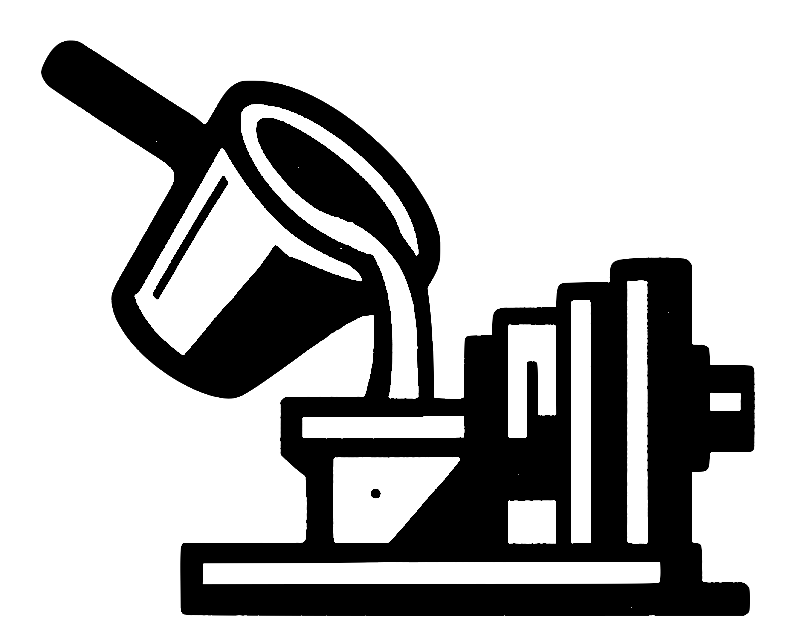
Die Casting Velocity Limits Explained
Introduction
Die casting velocity is the quiet dictator of casting quality. Too slow and you risk cold shuts; too fast and you shred the melt’s surface oxide, planting crack‑like bifilms throughout the part. Most scrap, rework and warranty failures trace back to this single parameter. In the pages that follow you will learn why surface speed—not bulk turbulence—sets the real limit; how the Weber, Froude and Reynolds numbers predict safe windows; and which simple runner and ingate tweaks keep velocity on the right side of the line. By the end, you will have a practical checklist to dial‑in velocity on any alloy, die size or machine.
The Physics Behind Critical Velocity
Liquid metal wears an ultra‑thin oxide skin. When the local inertial force exceeds surface tension, the skin tears and rolls into the flow—a defect factory. Engineers quantify this balance with the Weber number (We = ρv2L/σ). Experiments show that aluminium alloys stay below the tear threshold when We < 2. In practice that equals roughly 0.5 m s⁻¹ at the free surface for a 20 mm characteristic length. Campbell’s original work framed it plainly:
If the Weber number exceeds about two, we should expect oxide films to fold and entrain, creating bifilm defects.
This threshold is alloy‑agnostic because surface tension and density scale together. Magnesium, with lower density and tension, lands near the same 0.5 m s⁻¹ limit. Copper alloys sit closer to 0.4 m s⁻¹, while ferrous melts tolerate only 0.3 m s⁻¹ at the top surface.
Weber, Froude and Reynolds: Who Does What?
The Reynolds number (Re) flags bulk turbulence. High Re may boost fill uniformity without tearing oxides, provided the free surface stays calm. The Froude number (Fr) captures gravity‑driven sloshing in tall sprues; Fr < 1 prevents plunging waves. Finally, the Weber number controls micro‑folding of the oxide. Keep We low and the other two can run higher. A useful rule of thumb: design systems so We < 2 at every visible surface, Fr < 1 in vertical drops, and let Re float. Advanced CFD confirms that castings showing zero bifilm indicators maintain this order of magnitude separation.
Calculating Safe Ingate Velocity
The safe ingate speed equals the maximum surface speed at any point upstream. Use Bernoulli to convert height and runner pressure into velocity, then adjust gate area until vingate ≤ vcrit. For aluminium that means 0.5 m s⁻¹ if the ingate intersects free surface flow, or up to 1.5 m s⁻¹ when the cavity floods with no surface exposure. Many shops mistakenly quote higher “allowable” speeds from die fill simulations; those ignore oxide integrity. A 2023 study on automotive knuckles demonstrated a ten‑fold drop in X‑ray‑visible films when ingate velocity was trimmed from 2.0 m s⁻¹ to 0.9 m s⁻¹ [1].
Runner Geometry and Velocity Control
Runner height dictates head pressure, while runner width sets flow area. Dropping the height by 10 mm halves We without starving the die, provided the plunger keeps back‑pressure steady. Vortex runners swirl metal, stretching residence time and shedding kinetic energy before the ingate. Ceramic‑foam filters add a pressure drop that converts velocity into heat, taking the edge off the free jet. Place filters as close to the ingate as possible to prevent re‑acceleration. Trials on AlSi9Cu3 brackets showed 38 % porosity reduction with a 20 ppi filter and vortex runner combo at constant cycle time [2].
Special Cases: Thin Walls and High Fill Rates
Electronics housings and structural battery trays demand lightning fills. The trick is to flood from the bottom so the surface grows continuously; the initial flow front is the only surface that matters. Counter‑gravity vacuum assist excels here: the cavity fills metal‑first, air last. Where top‑gating is unavoidable, split the melt into multiple streams that meet travelling forward. Even if Re soars, the streams merge oxide‑side‑out, preserving surface integrity. Use CFD to verify that local We values remain low at all contact points.
On‑Machine Monitoring and Rapid Feedback
Shot sleeve pressure traces reveal real‑time velocity spikes. Install a piezo sensor near the biscuit; a sudden pressure dip followed by a spike signals cavity acceleration beyond design limits. Combine these traces with inline thermal imaging of the sprue to catch hot spots that indicate skin tearing. Modern HPDC presses can adjust first‑phase speed on the fly, shaving 0.2 m s⁻¹ mid‑shot and preventing entrainment without cycle loss. Data dashboards flag any shot whose calculated We exceeds its target, letting operators intervene before scrap snowballs.
Conclusion
Critical velocity rules die‑casting success. Keep Weber numbers below two at every visible surface, respect Froude limits on vertical drops, and design gates so ingate speed never drives surface flow beyond the oxide’s tensile strength. Runner tweaks, filters and bottom‑up fills make this surprisingly easy. Monitor each shot, react to spikes, and your scrap pile will shrink while tensile scatter tightens. Velocity may be invisible, but its discipline pays visible dividends.
References
- Park JY, Lee GH, Müller T, et al. Influence of ingate velocity on bifilm formation in aluminium high‑pressure die casting. Metals. 2023;13(11):2145. Available from: https://www.mdpi.com/2075-4701/13/11/2145
- Heidenreich J, Ma X, Braun S. Porosity reduction in AlSi9Cu3 brackets using vortex runners and ceramic filters. Int J Metalcast. 2024;18(1):77‑88. Available from: https://link.springer.com/article/10.1007/s40962-023-01422-1