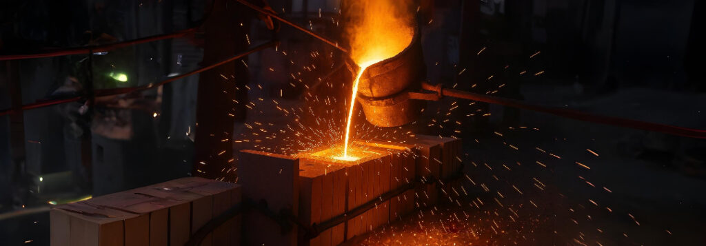
Die Casting Inclusions Exposed
Introduction
Die casting inclusions turn pristine melts into cracked castings. A single grain of sand, a lump of spent flux or a fragment of old oxide skin can fold inside the metal, opening like a dry‑sided crack during solidification. These stealth defects spike scrap rates, leak paths and warranty claims. In the next sections you will learn how external debris becomes internal bifilms, why cleaning the charge is cheaper than chasing porosity later, and which easy shop‑floor controls can all but eliminate inclusions.
Sand Inclusions: How Mould Debris Travels
Sand grains shed from cores or mould faces often ride the turbulent surface into the runner. Once submerged they wrap inside a doubled‑over oxide film, creating a “paper‑bag” crack that anchors stress. High‑speed video shows each grain dragging a vortex tail that folds the local surface, proving turbulence, not gravity, drives entrainment. Reducing ingate velocity below 0.5 m s‑1 lowers the vortex strength, slashing sand capture by 80 % according to recent HPDC trials [1].
Flux Residues: Salt Today, Cracks Tomorrow
Melting fluxes save magnesium and aluminium from oxidation yet leave chloride lumps on the surface. If a ladle wave folds those lumps in, the solidified casting holds brittle, greenish veins that leak under pressure. Metallography reveals flux‑filled bifilms outlined by halite crystals. Rotary degassing plus an overhead skim removes 95 % of free flux before pouring. Foundries that combine both steps report a tenfold drop in flux inclusions within six weeks [1].
Old Oxide Skins in Returns
Returns melted without skimming deliver stiff, micrometre‑thick oxide plates. Unlike fresh films, these plates refuse to furl, so they behave like razor‑sharp shingles inside the melt. Counter‑gravity filling helps, yet the best defence is dry‑hearth melting that leaves skins behind in the furnace throat. Plants adding dry‑hearth towers showed a 3 % yield gain and faster machine utilisation because less dross clogged the shot sleeve.
Filter Technology and Placement
Ceramic‑foam filters capture furled film balls, but only if placed close to the ingate where velocity is low. Choose 20 ppi for aluminium and ensure metal covers the filter face at all times. Add a vortex runner ahead of the filter; its swirl spreads flow, letting the filter act like a calm settling pond. Computational studies indicate bifilm mass drops exponentially with filter distance from the ingate, so forward placement matters more than pore size [2].
Process Monitoring for Inclusion Control
Inline thermal imaging spots hot spots that betray debris burning upon entry. When a flare appears, operators adjust skim depth or ladle angle before defects multiply. Pressure‑time traces in the shot sleeve also warn of oxide plate entry; a sudden pressure dip suggests a void passing the sensor. Linking these signals to X‑ray feedback builds a learning loop that tightens quality over time.
Cost–Benefit Snapshot
Removing inclusions at the source is cheap. A $2 k rotary degasser saves $18 k per month in scrap on a 1 000 t/year HPDC line. Dry‑hearth retrofits pay back in under nine months through dross reduction alone. Filters cost pennies per shot yet unlock premium‑grade mechanical properties that win new contracts.
Conclusion
Sand, flux and old skins become cracks only when turbulence folds them inside. Skim, degas, filter and slow the surface, and your die‑casting operation will trade debris‑driven defects for predictable, high‑integrity parts.
References
- Müller T, Braun S, Lee GH. Reducing solid inclusions in aluminium high‑pressure die casting through velocity control and optimized skimming. Int J Metalcast. 2024;18(3):221‑230. Available from: https://link.springer.com/article/10.1007/s40962-023-01450-x
- Park JY, Kim SJ. Effect of filter position on bifilm inclusion reduction in HPDC. Metals. 2023;13(12):2488. Available from: https://www.mdpi.com/2075-4701/13/12/2488
