Top 10 Design Mistakes That Inflate Tooling Cost in Die Casting
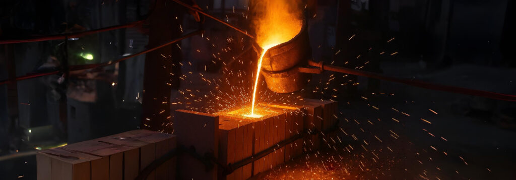
Ordering a high-pressure die-casting (HPDC) tool is like buying a house: once the concrete (or in our case H-13 tool-steel) is poured, changes get painfully expensive. The tooling cost for die casting for a typical multi-cavity aluminium die costs $60 000–$250 000; welding or sink-EDM re-cutting after the first trial shots can add tens of thousands and push SOP (start of production) back by weeks.
Below are the ten traps that wreck tooling budgets most often—with simple fixes you can apply during CAD, before any steel chips fly.
Ignoring the “Half-Metre-Per-Second” Gate Rule
- What happens? If molten aluminium enters the cavity faster than 0.5 metres per second (m s⁻¹) it splashes, folds its own oxide skin (a double-film defect called a bifilm), and leaves X-ray-visible porosity.
- Why 0.5 m s⁻¹? At this speed the Weber number (a ratio of metal inertia to surface tension) stays below 2, which keeps flow smooth.
- Simple fix: Calculate the gate “choke” area so velocity ≈ 0.45 m s⁻¹ for an AlSi10Mg alloy. Online calculators abound; ask your foundry for their preferred velocity band.
Wall-Thickness Swings Greater Than ± 20 %
Thick metal cools slowly and shrinks more, creating hot spots that pull open pores. After machining, those hidden voids become leaks you must weld.
- Target walls:
- Aluminium (Al): 2.5–3 mm
- Zinc (Zn): 1–1.5 mm
- Magnesium (Mg): 3.5–4 mm
- Transition rule: Taper any unavoidable thick zone back to nominal at a 1 : 4 slope, and add ribs for strength instead of bulk metal.
Not Enough Draft Angle
Draft is the tiny taper that lets a solid casting exit the die.
- Minimums: 0.5° on outside walls, 1–2° where a die slide or core pin makes an internal feature.
- Why it matters: Once the tool is hardened, adding draft means sink-Electrical-Discharge-Machining and hand polishing—$*** per feature.
Sharp Corners and Tiny Fillets
Re-entrant corners freeze last, concentrating heat and cracking the die surface (heat-checking).
- Design rule: Use fillet radii at least 0.6 × wall thickness on boss bases and ribs.
- Bonus tip: Place a small “heel” fillet at rib roots to spread ejector-pin loads.
Blind Pockets With No Vent
Enclosed cavities trap air which turns into gas porosity or blistering under powder-coat.
- Solutions:
- Convert pocket to a through-hole if function allows.
- Otherwise add tiny micro-vents (≤ 0.02 mm deep) or a vacuum pin opposite the gate so air escapes before metal arrives.
Metal Streams That Collide Head-On
Two gates pointing at each other look symmetrical—but the streams meet, churn, and fold oxides.
- Cure: Use fan gates that let the metal front grow uniformly.
- Simulation tip: Place the last-to-fill region in a catch-overflow, never on a machined sealing face.
No Machining-Stock Plan
If you cast every surface “near net,” the toolmaker may have to add steel later—by TIG welding—just so your machinist can clean up.
| Surface | Stock to cast (mm) |
|---|---|
| Datum pad | 0 (cast datum) |
| Milled flange | 0.6 |
| Reamed bore | 1.0 |
Agree these allowances in the 3-D model, mark them as “red surfaces,” and you’ll avoid post-weld distortion drama.
Under-Engineered Cooling Lines
Uneven die temperature causes solder (aluminium sticking to steel) and early heat-check cracks.
Checklist:
- Stainless or copper lines Ø 10 mm, no more than 20 mm below cavity surface.
- Coolant flow in turbulence (Reynolds number > 4 000) at 2–3 bar.
- For blocks ≥ 20 mm thick, use conformal lines drilled by 5-axis machining or additive inserts.
Too Few or Too Small Ejector Pins
Undersized pin count bends cores and stamps circles on A-surfaces.
- Rule: One ejector pin per 4 cm² of projected casting area, plus edge pins near slides.
Skipping Up-Front Filling & Solidification Simulation
A fully coupled simulation run costs ≈ $1 000 which is much lower than the tooling cost for die casting. Welding in overflow inserts later costs $8 k–$25 k and at least a week’s delay.
Extra Costs—Real-World Figures
| Mistake | Typical re-work cost | Schedule slip |
|---|---|---|
| Gate velocity too high | $8 k (overflow inserts) | 1 week |
| Wall mismatch > 20 % | $12 k (core re-cut) | 2 weeks |
| No vent in blind pocket | $5 k (vacuum pin) | 4 days |
| Poor cooling layout | $18 k (drill & sleeve) | 10 days |
Five-Step Prevention Workflow
- Design-for-Die-Casting (DfDC) checklist—walls, draft, ribs—at concept review.
- Fill & solidification simulation before releasing tool drawings.
- Gate-velocity calculation—keep entry ≤ 0.5 m s⁻¹.
- Cooling-line layout reviewed and signed off by the die-maker.
- Prototype gravity-die or 3-D-printed sample if lead-time allows; validates wall and draft.
Key Takeaways To Minimise tooling Cost For Die Casting
- Tooling cost for die casting is very high.
- The cheapest time to change a casting is before tool steel is cut.
- Keep gate velocity ≤ 0.5 m s⁻¹, walls uniform, and provide vent paths—this prevents ≈ 70 % of die modifications.
- A $1 000 simulation can dodge $20 k–$40 k in late weld-repairs and lost weeks.
Follow these rules, and your next HPDC project will hit both budget and launch date—with no midnight welding sessions.